


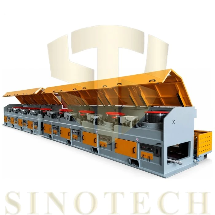
Dry Wire Drawing Machine
The Dry Wire Drawing Machine is designed for continuous multi-pass reduction of metal wire diameter using drawing dies and driven capstan blocks.
Description
Dry Wire Drawing Machine
Product Overview
The Dry Wire Drawing Machine is designed for continuous multi-pass reduction of metal wire diameter using drawing dies and driven capstan blocks. It processes wire rod into smaller-diameter wire for downstream manufacturing operations, including fastener production, wire mesh fabrication, nail making, and general steel wire processing.
The machine uses a series of drawing dies to reduce the cross-sectional area of the incoming wire. Individual drive motors control the capstan blocks, allowing drawing speed to be coordinated across successive passes. The drawing process also produces work hardening, which changes the mechanical properties of the wire according to its material grade, reduction schedule, lubrication, and processing conditions.
With an inlet wire diameter range of 5.5–14.0 mm and a finished wire diameter range of 1.6–5.0 mm, the machine supports different wire reduction requirements through appropriate block configurations and die arrangements. Selection depends on the starting material, target diameter, required tensile properties, production speed, and number of drawing passes.
Key Features
Multi-Pass Drawing Configuration
The machine uses 4–9 drawing blocks, depending on the selected configuration. Each pass reduces the wire diameter through a drawing die before the wire moves to the next block. The pass schedule must match the material grade, starting diameter, finished diameter, and required mechanical properties.
Individual AC Inverter Drive
Each block is equipped with an individual AC inverter drive according to the specified machine configuration. Variable-frequency speed adjustment allows the block speeds to be coordinated during drawing. Proper synchronization is important for maintaining wire movement and limiting excessive tension differences between successive blocks.
Capstan Wear Surfaces
The capstan blocks provide the traction and contact surfaces required for continuous wire drawing. Tungsten carbide coating can be specified where supported by the machine design. Coating composition, application process, hardness, and surface finishing should correspond to the actual capstan specification rather than being assumed identical across all models.
Cooling and Lubrication
Drawing dies and capstan contact areas generate heat during continuous operation. Die-box cooling and suitable drawing lubrication help manage friction and temperature. Water-cooled capstan blocks can be included where provided by the selected configuration. Lubricant type and application method should be matched to the wire material, drawing speed, and die design.
Industrial Machine Structure
The machine frame supports the drive assemblies, capstan blocks, and drawing components. Frame construction and alignment are important for maintaining the intended mechanical arrangement during operation. Protective guards and electrical safety devices should be specified according to the supplied machine design and applicable installation requirements.
Technical Specifications
|
Parameter |
Specification |
|
Machine Type |
Dry Wire Drawing Machine |
|
Inlet Wire Diameter |
5.5–14.0 mm |
|
Finished Wire Diameter |
1.6–5.0 mm |
|
Number of Drawing Blocks |
4–9 |
|
Capstan Block Diameter |
400–800 mm |
|
Drawing Speed |
12–25 m/s |
|
Main Motor Power |
15–55 kW per block, according to machine configuration |
|
Drive System |
Individual AC inverter drive per block |
|
Transmission |
Helical gearbox with oil-bath lubrication |
|
Drawing Method |
Multi-pass cold drawing through drawing dies |
|
Cooling Configuration |
Die-box water cooling; capstan water cooling where equipped |
|
Drawing Lubrication |
Dry-drawing lubricant compatible with the wire material and die system |
|
Wire Materials |
Carbon steel and other compatible metal wire grades |
|
Block Configuration |
4–9 blocks, selected according to the required reduction schedule |
Applications
Fastener Wire Production
The machine reduces suitable steel wire rod to the diameters required for bolts, screws, rivets, and other fastener manufacturing processes. The selected drawing schedule must provide wire suitable for the subsequent forming operation.
Wire Mesh and Fencing
Wire manufacturers can use the machine to prepare wire for welded mesh, chain-link fencing, and related products. Material grade, surface condition, and finished diameter requirements determine the appropriate configuration.
Nail Manufacturing
The machine can prepare compatible low-carbon steel wire for automatic nail-making lines. Finished wire diameter and mechanical properties should match the requirements of the downstream nail-forming equipment.
General Steel Wire Processing
Steel wire processors can use multi-pass drawing to produce smaller-diameter wire for industrial fabrication and other downstream applications. Specialized applications, including prestressed concrete wire, require separate verification of material suitability, process parameters, and finished-wire mechanical properties.
Frequently Asked Questions
Q: How is wire tension managed between drawing blocks?
A: Individual inverter drives allow the speed of each block to be adjusted. Where a dancer-arm or feedback-based control system is included, its operating method depends on the installed control configuration. Correct speed synchronization and a suitable reduction schedule are important for limiting excessive wire tension.
Q: What affects the achievable drawing speed?
A: Drawing speed depends on incoming and finished wire diameters, material grade, number of passes, die condition, lubrication, and cooling arrangements. The maximum rated speed should therefore be evaluated against the intended production specification rather than treated as a universal operating speed.
Q: What preparation is required before dry drawing?
A: Steel wire rod generally requires suitable surface preparation and drawing lubrication before entering the drawing dies. Mechanical descaling or an appropriate chemical pretreatment may be used according to the material and production process. The lubricant and coating system must be compatible with the drawing dies and subsequent manufacturing operations.
Q: What utilities are required for installation?
A: Installation requirements depend on the selected motor configuration, electrical supply, cooling system, and any pneumatic accessories. The plant layout should account for the machine footprint, power supply, cooling-water connections where applicable, lubricant handling, wire payoff, and finished-wire take-up.
Request a Technical Quote
To select a suitable Dry Wire Drawing Machine, provide the following information:
Incoming wire material grade and diameter
Required finished wire diameter and tensile strength
Target production capacity in tons per day or required drawing speed
Required number of drawing passes, if established
Available power supply voltage and frequency
Cooling, lubrication, payoff, and take-up requirements
These details allow the machine configuration, drive power, block arrangement, and drawing process to be evaluated against the intended production requirements.
Hot Tags: dry wire drawing machine, China dry wire drawing machine manufacturers, factory, Abrasive Belt Steel Wire Derusting Machine, Advanced Wire Rod Grinding Descaler, Baling Wire Coil Winging Machine, Industrial Cartridge Dust Collector, Single Bale Wire Coil Winding Machine, Wet Type Fine Wire Drawing Machine
Send Inquiry
You Might Also Like


